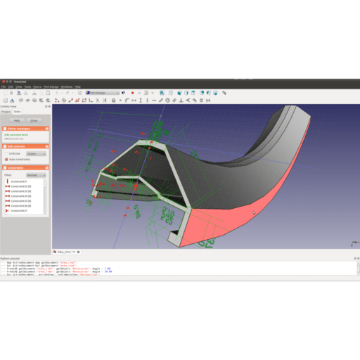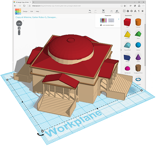

I want to talk about the sketching process in more detail before I tell you about one of FreeCAD’s killer features. If you’re interested in FreeCAD for the purpose of making simple three-dimensional parts using a 3D printer then this is probably as far as you need to go to master FreeCAD. Pocket Tool Converts Circle To Holeįinally, once you have a 3-D object you can replicate it linearly or in polar fashion, you can perform three-dimensional Boolean operations, etc. There are also subtractive equivalents that create simple grooves and helical grooves, subtractive sweeps, and lofts, etc. With just the pad and pocket tools, you can create an amazing number of objects, but of course, FreeCAD has some other 2-D to 3-D transformations that you can utilize as well: you can do a revolved extrusion, or even a helical extrusion, a sweep along a path, or a loft through two different profiles as additive actions. Once you have a three-dimensional object like a box you can create another sketch, and use that 2-D figure to create a ‘pocket’ or hole operation through the original 3-D object. A very common operation that you will use often is the ‘pad’ or ‘extrude’ tool: this operation takes a closed line 2-D figure, like a square, and extrudes it outward in the third dimension, creating a box or a cube. FreeCAD Design WindowįreeCAD works similarly to other CAD programs when it comes to designing a three-dimensional part: you start by creating a two-dimensional sketch and then perform some operation on the sketch to make it three-dimensional. The main window is where you view your assembly in 3D, and it is also where you create sketches, which are 2D drawings. At the top is the pane containing tool icons, on the left is a pane that is shared by parameter inputs and a structured tree view of your assembly, and at the bottom is a status window pane.

When you start the program you’re presented with a main window, and three auxiliary panes. I won’t be able to give you a detailed tutorial in this brief review, but I want to convey something about the flavor of what it is like to work with FreeCAD. This is a review of my experience using FreeCAD to design a multiple-part assembly in 3-D.įreeCAD has enormous capabilities serving various fields of engineering like architecture, optical design, robotics, and more, but 99% of the public is going to be interested in its mechanical part design capabilities, as I was. My employer graciously consented to cut the steel parts using their half-million-dollar water jet cutting machine, so I was off and running.
FREECAD REVIEW SOFTWARE
I decided to design a custom hand pump mounting platform that would clamp onto the well casing while providing the necessary offset, using an open source software program called FreeCAD from /…. I found that I could move the electric pump off to one side using something called a pitless adapter, but I could not find an off-the-shelf commercial solution for offsetting the hand pump. What is needed is a way to offset each pump assembly from the other. The problem is that both pumps expect to sit in the middle of the well casing when you use standard mounting parts. I bought the hand pump, but immediately ran into problems with the installation: hand pumps aren’t made to share space with an existing household electric pump down in the well casing. Grandpa was a big believer in the healthful properties of freshwater, pumped from a well.įorty years later I bought a rural property with its own well, and of course one of the first things I wanted was a hand pump put on the well. We didn’t go there to play on the swings, or throw a ball for a dog we went there to fill up glass jugs with water at a well with a hand pump. When I was a kid my grandpa used to take my sisters and me to a certain park in the Chicago Park District to perform a ritual on Sundays after church.


 0 kommentar(er)
